Prepare kube-ovn underlay physical networks
Kube-OVN Underlay container network relies on the support of the physical network for transmission. Before deploying the Kube-OVN Underlay network, please collaborate with the network administrator to plan and configure the physical network in advance to ensure network connectivity.
Instructions for use
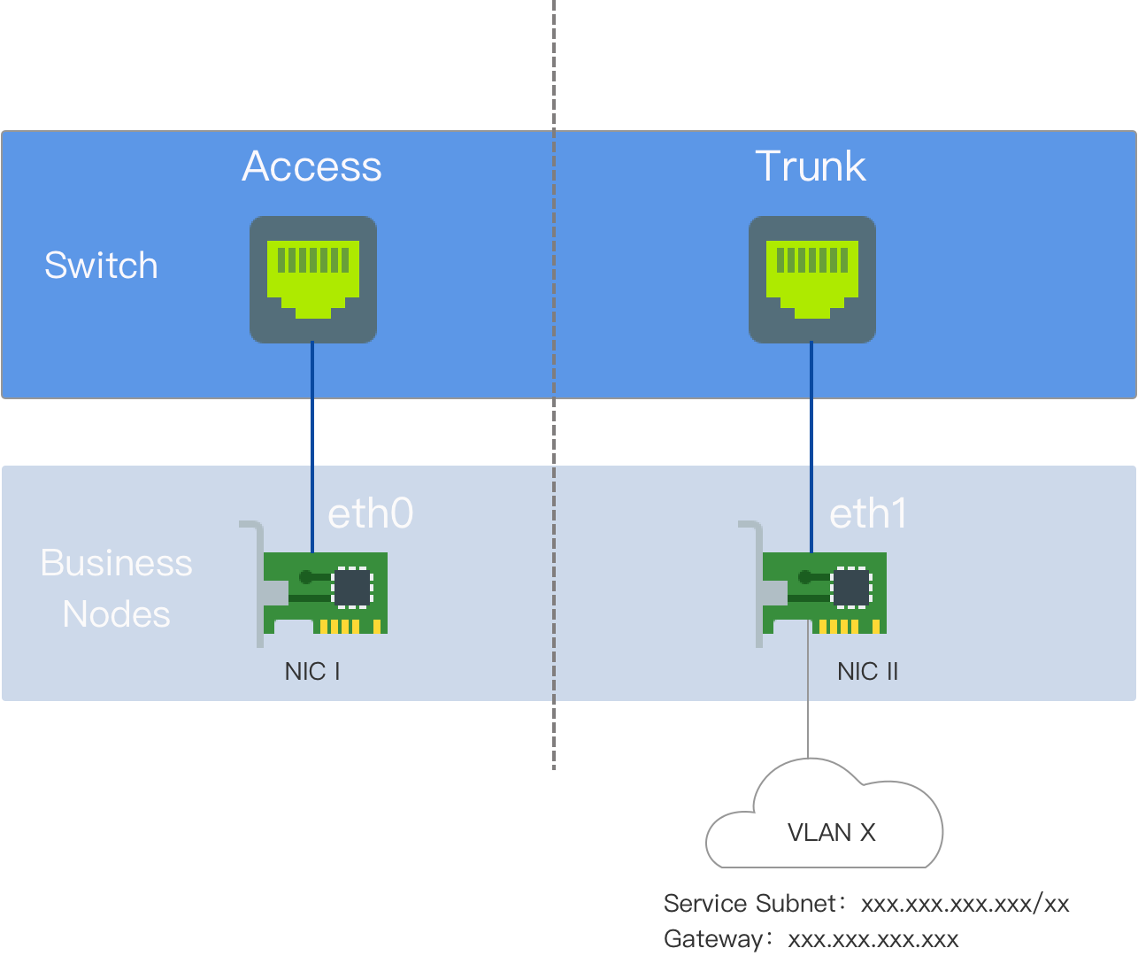
Kube-OVN Underlay requires a multi-NIC deployment, and the Underlay subnet must have exclusive access to a NIC. This NIC should not have any other type of traffic, such as SSH, which needs to use a different NIC.
Before using, please make sure that the node server has at least a dual NIC environment, and the recommended NIC speed is at least 10 Gbps or higher (e.g. 10 Gbps, 25 Gbps, 40 Gbps).
-
Network Card 1: The network card where the default route is located. It is configured with an IP address and connected to an external switch interface in Access mode.
-
NIC 2: The network card that is not on the default route and does not have an IP address configured. It is connected to the external switch interface and the configuration of the switch interface is set to Trunk mode. NIC 2 is dedicated to the Underlay subnet.
Explanation of nouns
VLAN (Virtual Local Area Network) is a data exchange technology that logically divides a local area network into segments (or smaller LANs) to achieve virtual workgroup.
The emergence of VLAN technology allows administrators to logically divide different users within the same physical LAN into different broadcast domains based on actual application requirements. Each VLAN consists of a group of computer workstations with similar needs and has the same attributes as a physically formed LAN. Since it is divided logically rather than physically, the workstations within the same VLAN are not restricted to the same physical range, meaning that these workstations can be in different physical LAN segments.
The main advantages of VLAN are:
-
Port separation. Even on the same switch, ports in different VLANs cannot communicate with each other. A physical switch can be used as multiple logical switches. It is commonly used to control mutual access between different departments and sites in a network.
-
Network security. Different VLANs cannot communicate directly, eliminating the insecurity of broadcast information. Broadcast and unicast traffic within a VLAN will not be forwarded to other VLANs, which helps control traffic, reduce equipment investment, simplify network management, and improve network security.
-
Flexible management. Changing the network to which a user belongs does not require replacing ports and connections, only changing the software configuration is needed.
Environment requirements
In Underlay mode, Kube-OVN bridges a physical network card to OVS and sends packets directly through this physical network card. The forwarding capabilities at the L2/L3 level depend on the underlying network devices. It is necessary to configure the corresponding gateway, VLAN, and security policies on the underlying network devices in advance.
-
Network Configuration Requirements
-
Kube-OVN checks the connectivity of the gateway through the ICMP protocol when starting containers, and the underlying gateway needs to be able to respond to ICMP requests.
-
For Service access traffic, Pods will first send packets to the gateway, which needs to have the ability to forward packets back to the local network segment.
-
When the switch or bridge has enabled the Hairpin feature, it is necessary to disable Hairpin. If using the VMWare virtual machine environment, you can directly set the Net.ReversePathFwdCheckPromisc of the VMWare host to 1, without the need to disable Hairpin.
-
Bridged network cards cannot be used for Linux Bridge.
-
Network card binding modes support Mode 0 (balance-rr), Mode 1 (active-backup), Mode 4 (802.3ad), and Mode 6 (balance-alb), with a recommendation to use 0 or 1. Other binding modes have not been tested, so please use them with caution.
-
-
IaaS (Virtualization) Layer Configuration Requirements
-
For the OpenStack VM environment, it is necessary to disable PortSecurity for the corresponding network ports.
-
For VMware’s vSwitch network, MAC Address Changes, Forged Transmits, and Promiscuous Mode Operation should all be set to Accept.
-
For public clouds such as AWS, GCE, Alibaba Cloud, etc., Underlay mode networking is not supported because they do not support user-defined MAC addresses.
-
Configuration examples
The node server in this example is a physical machine with dual network cards. Network card 1 is the default route network card, while network card 2 is the non-default route network card and does not have an IP address configured. It is exclusively used for the Underlay subnet. Network card 2 is connected to the external switch interface.
-
On the switch side, the interface connected to NIC 2 should be configured in Trunk mode and allowed to pass the corresponding VLAN.
-
Configure the gateway address for the cluster subnet on the corresponding vlan-interface interface. If dual-stack is required, the gateway address for IPv6 can also be configured simultaneously.
-
If the gateway is on a firewall, access from the node to the cluster-cidr network needs to be allowed.
-
Server network cards do not need any configuration.
Switch configuration
Configure VLAN Interface:
#
interface Vlan-interface74
  ip address 192.168.74.254 255.255.255.0   //IPv4 Gateway Address
  ipv6 address 2074::192:168:74:254/64  //IPv6 Gateway Address
#
Interface connected to the configuration and network card:
#
interface Ten-GigabitEthernet1/0/19
  port link mode bridge
  port link-type trunk  //Interface configuration Trunk Mode
  undo port trunk permit vlan 1
  port trunk permit vlan 74  //Allow configuration for VLAN Through
#
Checking network connectivity
Test whether NIC2 can communicate with the gateway address:
ip link add ens224.74 link ens224 type vlan id 74  //Network card name is ens224,VLAN IDis 74
ip link set ens224.74 up
ip addr add 192.168.74.200/24 dev ens224.74  //in Underlay Choose a test address within the subnet,This example uses 192.168.74.200/24
ping 192.168.74.254  //If possible Ping If you can ping the gateway, it means the physical environment meets the deployment requirements
ip addr del 192.168.74.200/24 dev ens224.74  //After the test is completed, the test address needs to be deleted
ip link del ens224.74  //After the test is completed, the sub-interface needs to be deleted
Platform configuration
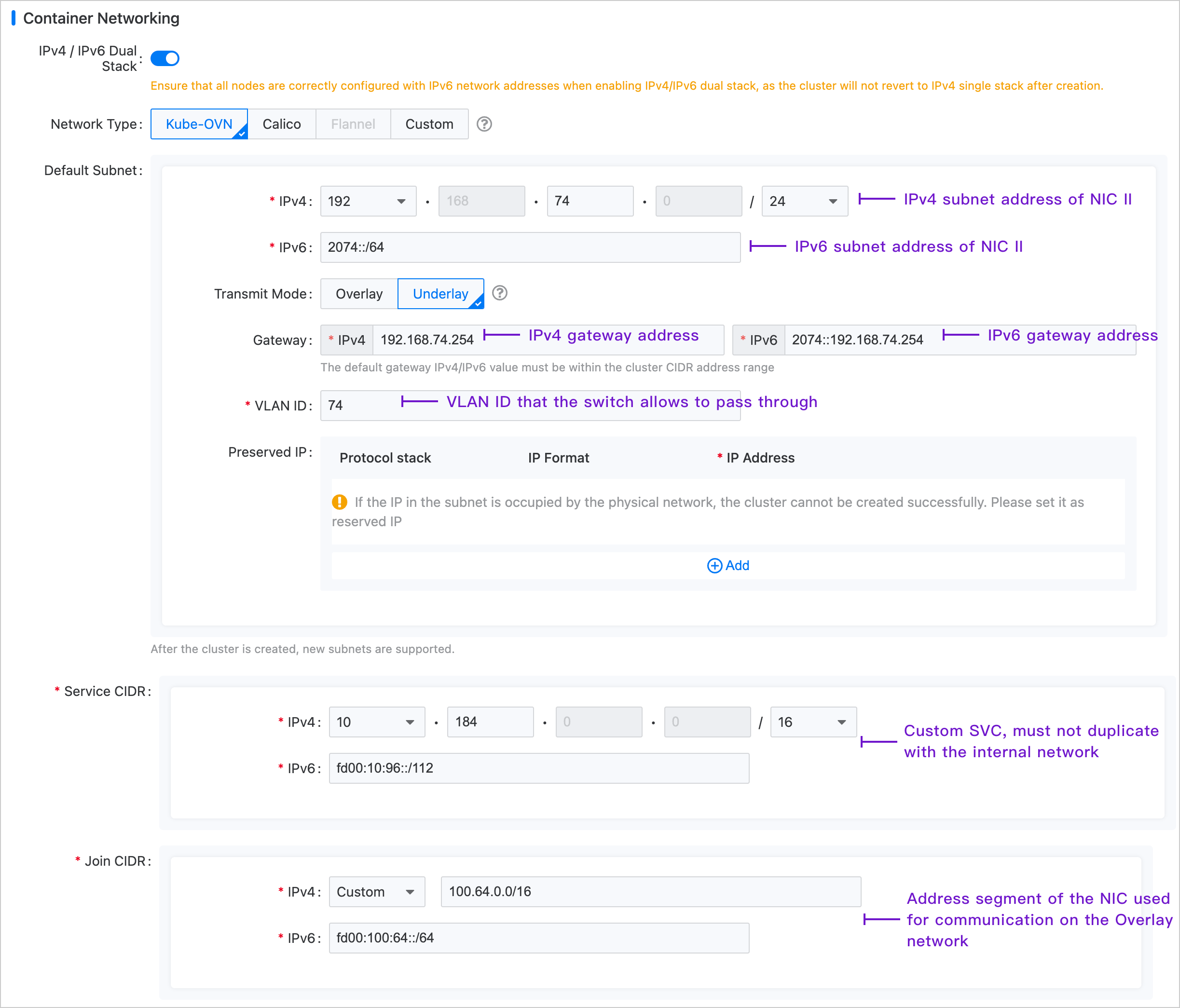
In the left navigation bar, click Clusters > Clusters, and then click Create cluster. For specific configuration steps, please refer to the Create a Cluster document. The configuration of the container network is shown in the following figure.
Note: The Join subnet has no practical significance in the Underlay environment. It is mainly used to create the Overlay subnet later on, providing the IP address range required for communication between nodes and Pods.